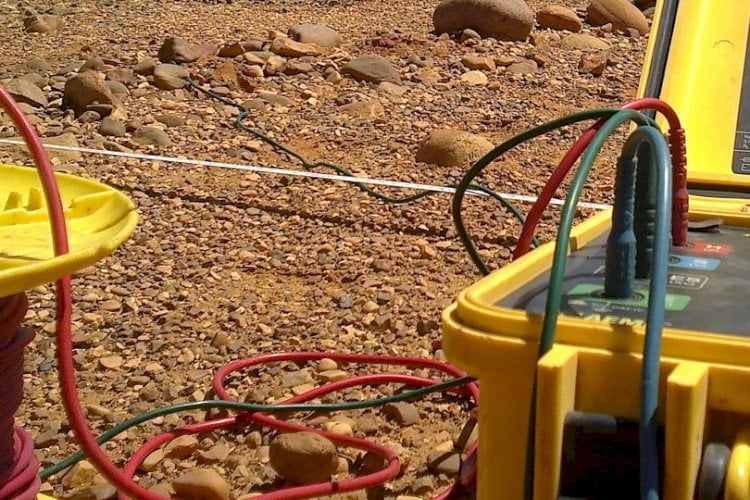
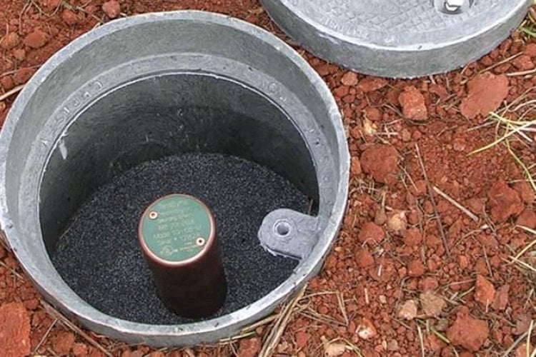
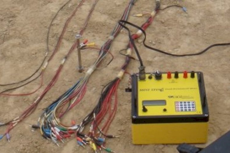
Soil resistivity testing is the process of measuring a volume of soil to determine the conductivity of the soil. The resulting soil resistivity is expressed in ohm-meter or ohm-centimeter.
Soil resistivity testing is the single most critical factor in electrical grounding design. This is true when discussing simple electrical design, to dedicated low-resistance grounding systems, or to the far more complex issues involved in Ground Potential Rise Studies (GPR). Good soil models are the basis of all grounding designs and they are developed from accurate soil resistivity testing.
Wenner Soil Resistivity Testing and Other 4-Point Tests
The Wenner 4-point Method is by far the most used test method to measure the resistivity of soil. Other methods do exist, such as the General and Schlumberger methods, however they are infrequently used for grounding design applications and vary only slightly in how the probes are spaced when compared to the Wenner Method.
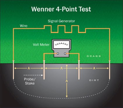
Wenner 4-Point Test
Electrical resistivity is the measurement of the specific resistance of a given material. It is expressed in ohm-meters and represents the resistance measured between two plates covering opposite sides of a 1 m cube. This soil resistivity test is commonly performed at raw land sites, during the design and planning of grounding systems specific to the tested site.
The soil resistivity test spaces four (4) probes out at equal distances to approximate the depth of the soil to be tested. Typical spacings will be 1’, 1.5’, 2’, 3’, 4.5’, 7’, 10’, etc., with each spacing increasing from the preceding one by a factor of approximately 1.5, up to a maximum spacing that is commensurate with the 1 to 3 times the maximum diagonal dimension of the grounding system being designed, resulting in a maximum distance between the outer current electrodes of 3 to 9 times the maximum diagonal dimension of the future grounding system. This is one “traverse” or set of measurements, and is typically repeated, albeit with shorter maximum spacings, several times around the location at right angles and diagonally to each other to ensure accurate readings.
The basic premise of the soil resistivity test is that probes spaced at 5’ distance across the earth, will read 5’ in depth. The same is true if you space the probes 40’ across the earth, you get a weighted average soil resistance from 0’ down to 40’ in depth, and all points in between. This raw data is usually processed with computer software to determine the actual resistivity of the soil as a function of depth.
Conducting a Wenner 4-point (or four-pin) Soil Resistivity Test
The following describes how to take one “traverse” or set of measurements. As the “4-point” indicates, the test consists of 4 pins that must be inserted into the earth. The outer two pins are called the Current probes, C1 and C2. These are the probes that inject current into the earth. The inner two probes are the Potential probes, P1 and P2. These are the probes that take the actual soil resistance measurement.
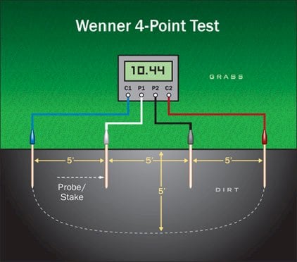
In the following Wenner 4-Point Test Setup diagram, a probe C1 is driven into the earth at the corner of the area to be measured. Probes P1, P2, & C2 are driven at 5’, 10’ & 15’ respectively from rod C1 in a straight line to measure the soil resistivity from 0’ to 5’ in depth. C1 & C2 are the outer probes and P1 & P2 are the inner probes. At this point, a known current is applied across probes C1 & C2, while the resulting voltage is measured across P1 & P2. Ohm’s law can then be applied to calculate the measured apparent resistance.
Probes C2, P1 & P2 can then be moved out to 10’, 20’ & 30’ spacing to measure the resistance of the earth from 0’ to 10’ in depth. Continue moving the three probes (C2, P1 & P2) away from C1 at equal intervals to approximate the depth of the soil to be measured. Note that the performance of the electrode can be influenced by soil resistivities at depths that are considerably deeper than the depth of the electrode, particularly for extensive horizontal electrodes, such as water pipes, building foundations or grounding grids.
Soil Resistance Meters
There are basically two types of soil resistance meters: Low-Frequency and High-Frequency models. Both meter types can be used for 4-point & 3-point testing, and can even be used as standard (2-point) volt meter for measuring common soil resistivity.
Care should always be given when selecting a soil resistance meter, as the electronics involved in signal filtering are highly specialized. Electrically speaking, the earth can be a noisy place. Overhead power lines, electric substations, railroad tracks, various signal transmitters and many other sources contribute to signal noise found in any given location. Harmonics, 60 Hz background noise, and magnetic field coupling can distort the measurement signal, resulting in apparent soil resistivity readings that are larger by an order of magnitude, particularly with large spacings. Selecting equipment with electronic packages capable of discriminating between these signals is critical.
High-Frequency soil resistance meters typically use a pulses operating at 128 pulses per second, or other pulse rates except 60. These High-Frequency meters typically suffer from the inability to generate sufficient voltage to handle long traverses and generally should not be used for probe spacings greater than 100 feet. Furthermore, the High-Frequency signal flowing in the current lead induces a noise voltage in the potential leads, which cannot be completely filtered out: this noise becomes greater than the measured signal as the soil resistivity decreases and the pin spacing increases. High-Frequency meters are less expensive than their Low-Frequency counterparts, and are by far the most common meter used in soil resistivity testing.
Low-Frequency meters, which actually generate low frequency pulses (on the order of 0.5 to 2.0 seconds per pulse), are the preferred equipment for soil resistivity testing, as they do away with the induction problem from which the High-Frequency meters suffer. However they can be very expensive to purchase. Depending upon the equipment’s maximum voltage, Low-Frequency meters can take readings with extremely large probe spacings and often many thousands of feet in distance. Typically, the electronics filtering packages offered in Low-Frequency meters are superior to those found in High-Frequency meters. Caution should be taken to select a reputable manufacturer.
Data Analysis
Once all the soil resistivity data is collected, the following formula can be applied to calculate the apparent soil resistivity in ohm-meters:
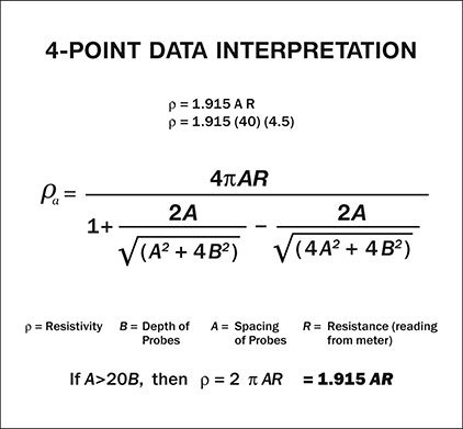
For example, if an apparent soil resistance of 4.5 ohms is at a 40-foot spacing, the soil resistivity in ohm-meters would be 344.7. Figure 11 shows the entire soil resistivity formula in detail. One refers to “apparent” resistivity, because this does not correspond to the actual resistivity of the soil. This raw data must be interpreted by suitable methods in order to determine the actual soil resistivity.
Shallow Depth Readings
Shallow depth readings, as little as 6” in depth, are exceedingly important for most, if not all, grounding designs. As described above, the deeper soil resistivity readings are actually weighted averages of the soil resistivity from the earth surface down to depth, and include all the shallow resistance readings above it. The trick in developing the final soil model is to pull out the actual resistance of the soil at depth, and that requires “subtracting” the top layers from the deep readings. The following figure demonstrates how the shallowest readings impact deeper ones below it.
As you can see in the following diagram, if you have a 5’ reading of 50 ohm-meters and a 10’ reading of 75-ohmmeter soil, the actual soil resistivity from 5’ to 10’ might be 100 ohm-meters (the point here is to illustrate a concept: pre-computed curves or computer software are needed to properly interpret the data). The same follows true for larger pin spacings. The shallowest readings are used over and over again in determining the actual resistivity at depth.
Shallow depth readings of 6-inches, 1-foot, 1.5-feet, 2-feet and 2.5-feet are important for grounding design, because grounding conductors are typically buried at 1.5 to 2.5-feet below the surface of the earth. To accurately calculate how those conductors will perform at these depths shallow soil readings must be taken. These shallow readings become even more important when engineers calculate Ground Potential Rise, Touch Voltages and Step Voltages.
It is critical that the measurement probes and current probes be inserted into the earth to the proper depth for shallow soil resistivity readings. If the probes are driven too deep, then it can be difficult to resolve the resistivity of the shallow soil. A rule of thumb is that the penetration depth of the potential probes should be no more than 10% of the pin spacing, whereas the current probes must not be driven more than 30% of the pin spacing.
Deep Readings
Often, the type of meter used determines the maximum depth or spacing that can be read. A general guideline is that High-Frequency soil resistivity meters are good for no more than 100-feet pin spacings, particularly in low resistivity soils. For greater pin spacings, Low-Frequency soil resistivity meters are required. They can generate the required voltage needed to push the signal through the soil at deep distances and detect a weak signal, free of induced voltage from the current injection leads.
Soil Resistivity Test Location
Soil resistivity testing should be conducted as close to the proposed grounding system as possible, taking into consideration the physical items that may cause erroneous readings. There are two (2) issues that may cause poor quality readings:
- Electrical interference causing unwanted signal noise to enter the meter.
- Metallic objects ‘short-cutting’ the electrical path from probe to probe. The rule of thumb here is that a clearance equal to the pin spacing should be maintained between the measurement traverse and any parallel buried metallic structures.
Testing in the vicinity of the site in question is obviously important; however, it is not always practical. Many electric utility companies have rules regarding how close the soil resistivity test must be in order to be valid. The geology of the area also plays into the equation as dramatically different soil conditions may exist only a short distance away.
When left will little room or poor conditions in which to conduct a proper soil resistivity test, one should use the closest available open field with as similar geological soil conditions as possible.

