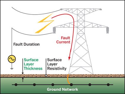
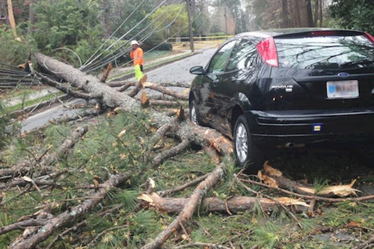
Ground Potential Rise (GPR) or Earth Potential Rise is a phenomenon that occurs when large amounts of electricity enter the earth. This is typically caused when substations or high-voltage towers fault, or when lightning strikes occur (fault current). When currents of large magnitude enter the earth from a grounding system, not only will the grounding system rise in electrical potential, but so will the surrounding soil as well.
The voltages produced by a Ground Potential Rise or Earth Potential Rise event can be hazardous to both personnel and equipment. As described earlier, soil has resistance known as soil resistivity which will allow an electrical potential gradient or voltage drop to occur along the path of the fault current in the soil. The resulting potential differences will cause currents to flow into any and all nearby grounded conductive bodies, including concrete, pipes, copper wires and people.
Ground Potential Rise Study
A Ground Potential Rise Study is the process of automated timed and/or continuous resistance-to ground measurement. These dedicated systems use the induced frequency test method to continuously monitor the performance of critical grounding systems. Some models may also provide automated data reporting. These new meters can measure resistance-to-ground and the current that flows on the grounding systems that are in use. Another benefit is that it does not require interruption of the electrical service to take these measurements.
Ground Potential Rise (GPR) Definitions
Ground Potential Rise or Earth Potential Rise (as defined in IEEE Standard 367) is the product of a ground electrode impedance, referenced to remote earth, and the current that flows through that electrode impedance.
Ground Potential Rise or Earth Potential Rise (as defined by IEEE Standard 80-2000) is the maximum electrical potential that a (substation) grounding grid may attain relative to a distant grounding point assumed to be at potential of remote earth. This voltage, GPR, is equal to the maximum grid current times the grid resistance.
Ground Potential Rise or Earth Potential Rise events are a concern wherever electrical currents of large magnitude flow into the earth. This can be at a substation, high-voltage tower or pole, or a large transformer. In cases where an Earth Potential Rise event may be of special concern, grounding precautions are required to ensure personnel and equipment safety. Electrical potentials in the earth drop abruptly around the perimeter of a grounding system, but do not drop to zero. In fact, in a perfectly homogeneous soil, soil potentials are inversely proportional to the distance from the center off the grounding system, once one has reached a distance that is a small number of grounding system dimensions away.
The Earth Potential formula is as follows:
- Earth Potential = Soil Resistivity x Current / (2 x PI x Distance)
Where Earth Potential is in volts, Soil Resistivity is in ohm-meters, Current is the current flowing into the soil from the grounding system, in amperes, PI is 3.14159… and Distance is in meters.
Probably the most commonly noted Ground Potential Rise or Earth Potential Rise event involves the death of cows in a field during a lightning strike. Imagine lightning striking the center of an open field where cows are standing. The current injected into the earth flows radially away from the strike point, in all directions, creating voltage gradients on the surface of the earth, also in a radial direction. All the cows facing the lightning strike would have their fore hooves closer to the strike point than their rear hooves. This would result in a difference of potential between their fore and rear legs, causing current to flow through their bodies, including the heart area, and killing the cow. On the other hand, those cows with their flanks turned towards the lighting strike would have a greater chance of surviving, as the distance between their fore legs and therefore the voltage applied between them, would be relatively small, resulting in a lesser current flow.
A Ground Potential Rise Study is typically conducted on substations and high-voltage towers to measure Earth Potential. Substations have relatively large grounding areas, especially when compared to high-voltage towers and poles. Towers and poles represent by far the most potentially dangerous and difficult Ground Potential Rise situations to handle and are often not protected, unless they are located in high exposure areas or have equipment installed at ground level at which service personnel might be required to work.
Ground Potential Rise Study
The primary purpose of a Ground Potential Rise Study is to determine the level of hazard associated with a given high-voltage location for personnel and/or equipment. When the degree of hazard is identified, the appropriate precautions must be made to make the site safe. To do this, the engineer must identify what the minimum grounding system for each location will be. The engineer must also take into consideration all local and federal guidelines, including utility company and other requirements.

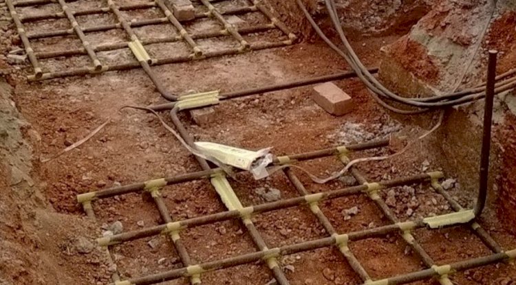
For example: Many utility companies require at a minimum that a simple ground ring be installed at least 18 inches below ground and 3 feet from the perimeter of all metal objects. This ground ring is also referred to as a counterpoise.
Once the minimum grounding system is identified, the engineer can run a Ground Potential Rise or Earth Potential Rise Analysis and identify the extent of any electrical hazards.
Typically, items reported in a Ground Potential Rise Study will include the following: the square footage, size and layout of the proposed grounding grid, resistance-to-ground of the proposed grounding system, the estimated fault current that would flow into the grounding system, Ground Potential Rise (in volts) at the site, 300 Volt Peak line, the X/R Ratio, and the fault clearing time in seconds. Step and touch potential voltages are usually computed as well, as these are the primary indicators of safety.
The grounding engineer needs three (3) pieces of information to properly conduct a Ground Potential Rise Study:
- Soil resistivity data from a Soil Resistivity Test
- Site drawings with the proposed construction
- Electrical data from the power company
Soil Resistivity Test
The soil resistivity test data should include apparent resistivity readings at pin spacings ranging from 0.5 or 1 ft to as many as three grounding grid diagonals, if practical. Touch and step voltages represent the primary concern for personnel safety. Understanding the characteristics of the soil at depths ranging from immediately underfoot to one or more grid dimensions is required for a cost-effective and safe grounding system to be designed.
Site Drawings
The proposed site drawings should show the layout of the high-voltage tower or substation, and any additional construction for new equipment that may be occurring on the site, including fencing and gate radius. Incoming power and Telco runs should also be included. In the case of high-voltage towers, the height and spacing of the conductors carried on the tower, and any overhead ground wires that may be installed on the tower, need to be detailed during the survey. This information is needed to properly address all the touch and step voltage concerns that may occur on the site.
Electric Utility Data
The electric utility company needs to provide electrical data regarding the tower or substation under consideration. This data should include the name of the substation or the number of the tower, the voltage level, the subtransient X/R ratio, and the clearing times. In the case of towers, the line names of the substations involved, the amount of current contributed by each substation in the event of a fault, and the type and positions of the overhead ground wires, if any, with respect to the phase conductors installed on each tower or pole. If overhead ground wires are present, tower or pole ground resistances along the line are of interest as well, be they measured, average or design values.
This information is important, as high-voltage towers have small ground area, yet handle very large amounts of electricity. Knowing if a tower has an overhead ground wire is important, because the overhead wire will carry away a percentage of the current, which will depend on the overhead ground wire type and ground resistances of adjacent towers, to other towers in the run, reducing the GPR event. Additionally, towers with overhead ground wires tend to have shorter clearing times. The same holds for substations: overhead ground wires on transmission lines and neutral wires on distribution lines can significantly reduce the magnitude of fault current that flows into the substation grounding system during fault conditions.
The following information is required from the utility company:
- Phase-to-ground fault current contributed by each power line circuit
- Fault clearing time
- Line voltage
- Subtransient X/R ratio
- The make/type/number of overhead ground wires on each tower/pole line and position with respect to the phase conductors
- Ground wire continuity and bonding configuration back to the tower and substation
- The average distance from tower-to-tower and tower-to-substation
- Typical tower/pole ground resistance: measured or design values
As-built drawings are often acquired and are useful for towers with existing grounding systems. They are also useful in the case of modifications and upgrades to existing substations, which will have extensive grounding systems already installed.
Personnel Safety During Ground Potential Rise or Earth Potential Rise Events
The grounding engineer will be required to develop safety systems to protect any personnel working where Ground Potential Rise hazards are known to exist. Federal Law mandates that all known hazards must be eliminated from the work place for the safety of workers. It is the engineer’s choice on which voluntary standards to apply in order to comply with the law. Federal law 29 CFR 1910.269 specifically states that Step and Touch Potentials must be eliminated on transmission and distribution lines that include any related communication equipment.
Substations are always considered workplaces and Step and touch Potentials must be eliminated. Transmission and distribution towers or poles are not always considered work places and therefore are often exempt from these requirements. Take, for example, a lonely tower on a mountain side or in the middle of the desert: these towers are not typically considered workplaces. However, any high-voltage tower or pole becomes a workplace as soon as equipment is installed that is not related to the electric utility company and requires outside vendors to support the new equipment. Cellular telecommunications, environmental monitoring, and microwave relay equipment are good examples of equipment that, when installed on a high-voltage tower, turns the tower into a work place. This would make the elimination of Step and Touch Potentials required.
Hazardous Voltages
Fibrillation Current is the amount of electricity needed to cause cardiac arrest, from which recovery will not spontaneously occur, in a person and is a value based on statistics. IEEE Std 80-2000 provides a method to determine the pertinent value of Fibrillation Current for a safety study, along with a good explanation of how it is derived. Many different methods exist for calculating Fibrillation Current; however the 50kg IEEE method is the most commonly used in North America. The formula used shows that the Fibrillation Current level is inversely proportional to the square root of the fault duration; however, it must be increased by a correction factor, based on the subtransient X/R ratio, which can be quite large for shorter fault durations. If personnel working at a site during fault conditions experience voltages that will cause a current less than the Fibrillation Current to flow in their bodies, then they are considered safe. If a worker will experience a greater voltage than is acceptable, additional safety precautions must be taken.
The subtransient X/R ratio at the site of the fault is important in calculating the acceptable Fibrillation Current and to determine the maximum allowable Step and Touch Potentials that can occur at any given site.
Fault Duration is a very necessary piece of data for properly calculating maximum allowable Step and Touch Potentials. The Fault Duration is the amount of time required for the power company to shut off the current in the event of a fault.
Ultimately the engineer must determine two (2) things:
- The site-specific maximum allowable voltage that a person can safely withstand
- The actual voltages that will be experienced at the site during a fault
Each site will have different levels of voltages for both of the above. Unfortunately, we cannot simply say that a human being can withstand X-level of voltages and use that value all the time, since this voltage is determined by the surface layer resistivity, the fault duration and the subtransient X/R ratio. Additionally as each site has different fault durations and different soil conditions, it is critical that calculations be made for each and every possible fault location.


