Grounding Electrode Test Wells
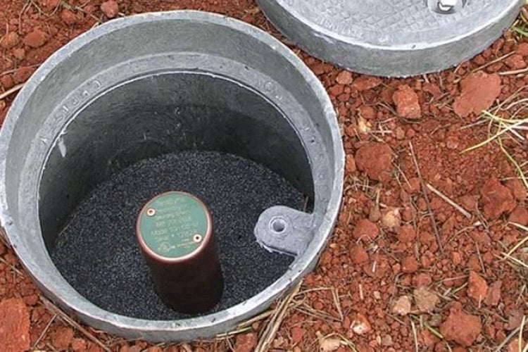
The purpose of a ground test well is two-fold: to be able to quickly and easily measure resistance-to-ground of the grounding electrode and/or to measure point-to-point continuity (resistance) from one electrode to another.
The first part, resistance-to-ground, is a measurement of the total resistance to the flow of electricity that the earth is providing against the ground system under test. As the 3-point fall-of-potential method is not usable for any active grounding system, only the clamp-on or induced frequency method can be used for testing the resistance-to-ground of electrodes with a test well. This involves a hand-held meter with large jaws that are “clamped” around a grounding conductor under test, thus the need for a test well.
The second part, which is simple point-to-point continuity (resistance) measurements, can be done even at an improperly installed test well. Point-to-point testing from a ground test well back to a reference point can be very valuable for understanding the integrity and conductivity of a grounding system. The goal is to install ground test wells that are capable of allowing both measurements.
Improper Installation of a Ground Test
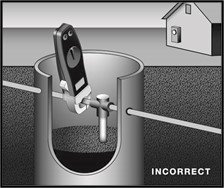
One of the most common ways ground test wells are improperly-installed, as seen in the image on the left. In this scenario, the installer has simply provided physical access to the ground ring with a ground rod “T-welded” into the loop. This scenario allows us to clamp on to the ground loop conductor above the ground rod itself. However, the signal from the clamp-on ground resistance meter will merely travel around the copper conductor in a loop, and is never forced to travel through the earth itself. This test well is improperly installed and will not allow accurate resistance-to-ground measurement.
In the image below, we see the second most common way test wells are improperly-installed, and this is with a twist or “loop” added to the ground conductor. As you can see, this scenario is actually the exact same thing as Scenario #1, although quite possibly easier to clamp the meter around the conductor.
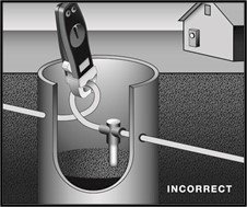
The downside is, that this twist in the conductor is a major violation of the rules listed in NFPA 780 Lightning Standards, and the Motorola R56, (and several IEEE standards) in regards to the self-induced coupling effects that high-current, short-duration faults can have on ground systems.
When lightning strikes or a major short circuit fault occurs, a large and powerful magnetic field will form as the current travels through the ground conductor. Any conductors with a ‘tight radius’ are subject to burn-open due to cross-coupling of the magnetic fields. The bottom line is that this test well is improperly installed and not only is it at risk of critical failure under electrical stress, but it will not allow an accurate resistance-to-ground measurement test.
Proper Installation of a Ground Test Well
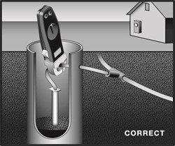
In the figure below we can see that installing a grounding electrode in a test well simply requires a short conductor extension or “pig-tail” to be added connecting the top of the electrode to the ground loop. While this does require two welds instead of just a single exothermic weld, it is often less labor-intensive as the conductor extension is easier to work with than the ground loop. In this setup, we can see that the clamp-on meter has easy access and that the injected signal will be forced down the ground rod and through the earth, enabling an accurate resistance-to-ground reading of that ground rod. And of course, accurate point-to-point testing can be conducted as well.
When lightning strikes or a major short circuit fault occurs, a large and powerful magnetic field will form as the current travels through the ground conductor. Any conductors with a ‘tight radius’ are subject to burn-open due to cross-coupling of the magnetic fields.
The bottom line is that this test well is improperly installed and not only is it at risk of critical failure under electrical stress, but it will not allow an accurate resistance-to-ground measurement test.
The Engineering Experts at E&S Grounding Solutions
Let's Talk! Schedule a FREE Phone Consultation Today.
Wherever you're located, learn how good a fit we are for your project.

