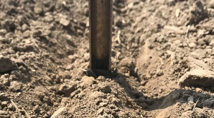
Grounding Plates
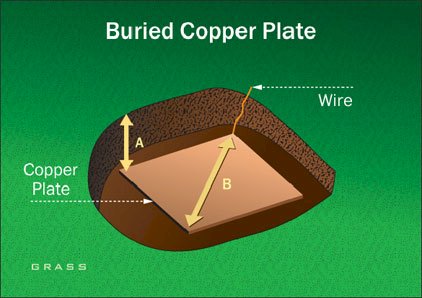
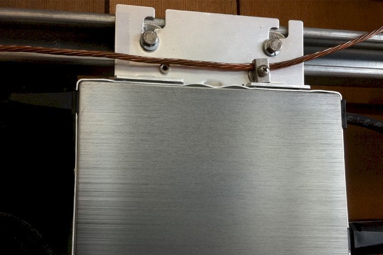
Grounding plates are typically thin copper plates buried in direct contact with the earth. The National Electrical Code requires that ground plates have at least 2 ft2 of surface area exposed to the surrounding soil. Ferrous materials must be at least 0.20 inches thick, while non-ferrous materials (copper) need only be 0.060 inches thick. Grounding plates are typically placed under poles or supplementing buried ground rings.
Grounding plates should be buried at least 30 inches below grade level. While the surface area of grounding plates is greatly increased over that of a driven rod, the zone of influence is relatively small as shown in “B”. The zone of influence of a grounding plate can be as small as 17 inches. This ultra-small zone of influence typically causes grounding plates to have a higher resistance reading than other electrodes of the same mass. Similar environmental conditions, which lead to the failure of the driven rod, also plague the grounding plate, such as corrosion, aging, temperature, and moisture.
Concrete Encased Electrodes
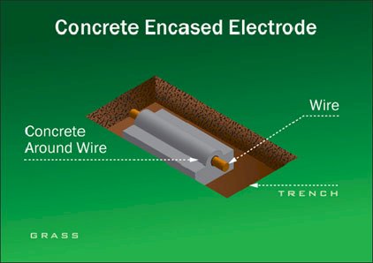
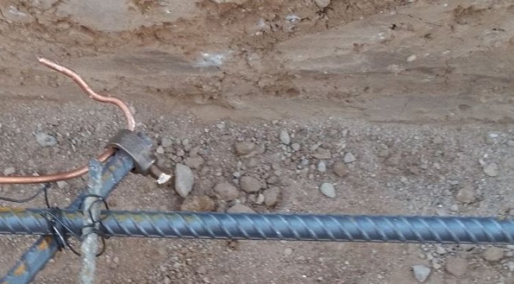
Originally, Ufer grounds were copper electrodes encased in the concrete surrounding ammunition bunkers. In today’s terminology, Ufer grounds consist of any concrete-encased electrode, such as the rebar in a building foundation, when used for grounding, or a wire or wire mesh encased in concrete.
The National Electrical Code requires that Concrete Encased Electrodes use a minimum No. 4 AWG copper wire at least 20 feet in length and encased in at least 2 inches of concrete. The advantages of concrete encased electrodes are that they dramatically increase the surface area and degree of contact with the surrounding soil. However, the zone of influence is not increased; therefore the resistance to ground is typically only slightly lower, than the wire would be without the concrete.
Concrete encased electrodes also have some significant disadvantages. When an electrical fault occurs, the electric current must flow out of the conductor and through the concrete to get to the earth. Concrete, by nature retains a lot of water, which rises in temperature as the electricity flows through the concrete. If the concrete encased electrode is not sufficient to handle the total current, the boiling point of the water may be reached, resulting in an explosive conversion of water into steam. Many concrete encased electrodes have been destroyed, after receiving relatively small electrical faults. Once the concrete cracks apart and falls away from the conductor, the concrete pieces act as a shield preventing the copper wire from contacting the surrounding soil, resulting in a dramatic increase in the resistance-to-ground of the electrode.
There are many new products available on the market designed to improve concrete encased electrodes. The most common are modified concrete products that incorporate conductive materials into the cement mix, usually carbon. The advantage of these products is that they are fairly effective in reducing the resistivity of the concrete, thus lowering the resistance-to-ground of the electrode encased. The most significant improvement of these new products is in reducing heat buildup in the concrete during fault conditions, which can lower the chances that steam will destroy the concrete encased electrode. However, some disadvantages are still evident.
Again, these products do not increase the zone-of-influence and as such, the resistance-to-ground of the concrete encased electrode, is only slightly better than what a bare copper wire or driven rod would be in the ground. Also a primary concern regarding enhanced grounding concretes is the use of carbon in the mix. Carbon and copper are of different nobilities and will sacrificially corrode each other over time. Many of these products claim to have buffer materials, designed to reduce the accelerated corrosion of the copper, caused by the addition of carbon into the mix. However, few independent long-term studies are being conducted to test these claims.
Ufer Ground or Building Foundations
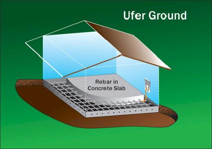
Ufer Grounds or building foundations may be used provided that the concrete is in direct contact with the earth (no plastic moisture barriers), that rebar is at least 0.500 inches in diameter and that there is a direct metallic connection from the service ground to the rebar buried inside the concrete.
This concept is based on the conductivity of the concrete and the large surface area, which will usually provide a grounding system, which can handle very high current loads. The primary drawback occurs during fault conditions, if the fault current is too great compared with the area of the rebar system, when moisture in the concrete superheats and rapidly expands, cracking the surrounding concrete, threatening the integrity of the building foundation. Another important drawback to the Ufer ground is that they are not testable under normal circumstances, as isolating the concrete slab in order to properly perform resistance-to-ground testing, is nearly impossible.
The metal frame of a building may also be used as a grounding point, provided that the building foundation meets the above requirements, and is commonly used in high-rise buildings. It should be noted that many owners of these high-rise buildings are banning this practice and insisting that tenants run ground wires all the way back to the secondary service locations on each floor. The owners will already have run ground wires from the secondary services back to the primary service locations and installed dedicated grounding systems at these service locations. The goal is to avoid the flow of stray currents, which can interfere with the operation of sensitive electronic equipment.
Water Pipes
Water pipes have been used extensively over time as a grounding electrode. Water pipe connections are not testable and are unreliable due to the use of tar coatings and plastic fittings. City water departments have begun to specifically install plastic insulators in the pipelines, to prevent the flow of current and reduce the corrosive effects of electrolysis. The National Electrical Code requires that at least one additional electrode be installed, when using water pipes as an electrode. There are several additional requirements including:
- 10 feet of the water pipe is in direct contact with the earth,
- Joints must be electrically continuous,
- Water meters may not be relied upon for the grounding path,
- Bonding jumpers must be used around any insulating joints, pipe or meters,
- Primary connection to the water pipe must be on the street side of the water meter,
- Primary connection to the water pipe shall be within five feet of the point of entrance to the building.
The National Electrical Code requires that water pipes be bonded to ground, even if water pipes are not used as a grounding electrode.
Electrolytic Electrode

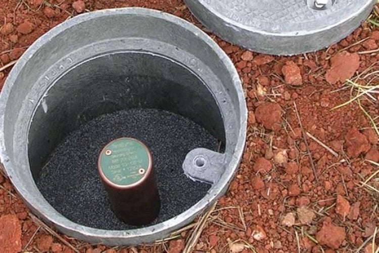
The electrolytic electrode was specifically engineered to eliminate many of the drawbacks found in other types of grounding electrodes. The electrolytic electrode consists of a hollow copper shaft, filled with salts and desiccants whose hygroscopic nature draws moisture from the air. The moisture mixes with the salts to form an electrolytic solution, which continuously seeps into the surrounding backfill material, keeping it moist and high in ionic content. The electrolytic electrode is installed into an augured hole and is typically backfilled with a conductive material, such as bentonite clay. The electrolytic solution and the backfill material work together to provide a solid connection between the electrode and the surrounding soil, that is free from the effects of temperature, environment, and corrosion. The electrolytic electrode is the only grounding electrode that improves with age. All other electrode types will have a rapidly increasing resistance-to-ground as the season’s change and the years pass. The drawbacks to these electrodes are the cost of installation and the cost of the electrode itself.
Various backfill products are available in the market place; the primary concern should be if the product protects the electrode from corrosion and improves its conductivity. Carbon-based products should be avoided as they will corrode the copper over time.
There are generally two (2) types of electrolytic electrodes that one can install, ones that use sodium chloride (table or rock salt), and those that use magnesium sulfate (Epsom salt). There are advantages and disadvantages for each type. The electrolytic electrodes that use sodium chloride have very long life-spans (30 to 50 years) and as such are often sealed closed as there is no need to access the tube. The disadvantage is that very little salt actually enters the surrounding soil, so the time it takes to lower the resistance-to-ground can be very long (years if not decades). The electrolytic electrodes that use magnesium sulfate come with an access cap at the top of the electrode, as the magnesium sulfate will rapidly dissolve away and out of the tube entering the surrounding soil, thus quickly lowering the resistance-to-ground. The disadvantages of magnesium sulfate electrodes is that they require annual maintenance to refill the salts in the tube, and if the magnesium sulfate is exposed to high-heat, such as from a lightning strike, chemical reactions can occur resulting in some toxic substances. The MSDS sheet for magnesium sulfate should be consulted prior to use. Some grounding engineers have installed electrolytic electrodes with magnesium sulfate for the first few years of operation so as to rapidly lower the resistance-to-ground, and then switched over to a sodium chloride and desiccant mix for the long life and low-maintenance once the surrounding soil has been saturated with conductive materials.
The Engineering Experts at E&S Grounding Solutions
Let's Talk! Schedule a FREE Phone Consultation Today.
Wherever you're located, learn how good a fit we are for your project.

