Milan asked:
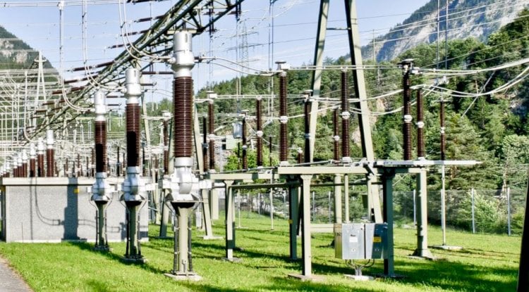
How do I calculate the fault current an electrical substation grounding design? I am trying to understand how to design a substation grounding system and fault current is something I am not getting. For example, for a small substation with some transformers, if there is a fault in the system how will the fault current flow into the grounding system?
Our Answer:
An important concept to remember about transformers, is that transformers are actually “two halves of two circuits”.
For example, let say you have a 11kV-433V, 3-phase, 500kVA transformer. Somewhere located many kilometers away, you would find the source transformer that is sending you the 11kV power, yes? So if the primary side of your transformer faults, the fault current must go back to its source in order to clear the fault, no matter where on the planet that source is located.
In a common household or industrial electrical system, we are not allowed to use the earth/soil as a fault current path (with the exception of TT Systems, where we can prove less than 200 ohms on the Zs test). Note: TT Systems can be dangerous and are actually banned in NEC-based countries.
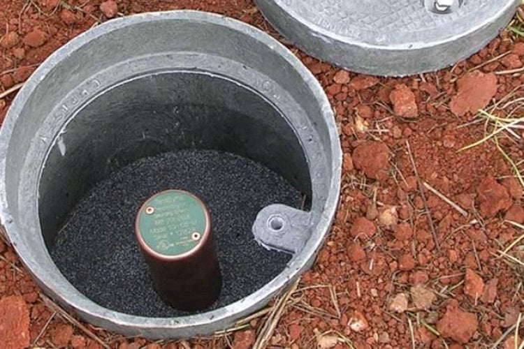
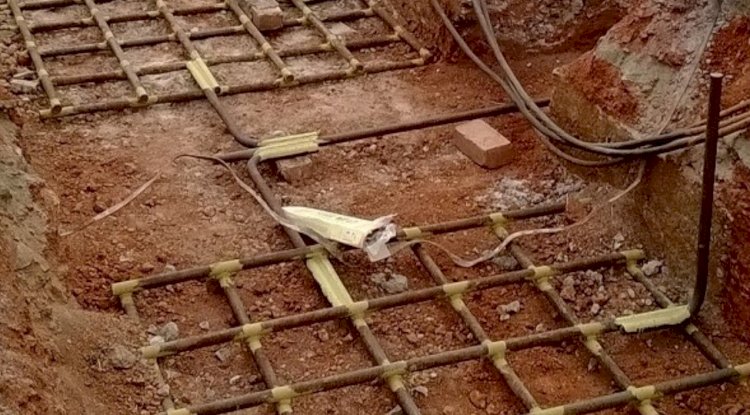
However, at the level of the electrical provider, substations are allowed to use the earth as a conductor. So, if the primary side of your 11kV-433V transformer were to fault, the fault current would enter your substation’s protective earthing system, travel through the earth/soil many kilometers to wherever the source transformer is located, and up that transformers protective earthing system. It would then travel through the earthed center-tap, causing a massive increase in current through the windings, where the circuit breaker would sense the increase and turn off the circuit.
If there was a protective earth wire stretched from the substation (and sometimes there is), much of the current will travel through that wire(s), instead of through the earth/soil. This is important to understand because the protective earthing systems have a resistance-to-earth that allows hazardous voltages to form. These voltages that form during electrical faults can injure and even kill persons working in or near the substation. Hazardous Step & Touch Voltages can form on fences, door frames, chassis of electrical components, and other normally-non-current-carrying metallic objects.
Careful studies of the step and touch voltage hazards at substations are mandated under IEC 60050-195 (IEEE Std. 80 in NEC countries). Human safety at these substations is typically governed carefully, as the public outside of the facility can be injured during electrical faults. Persons touching the outside of the substation’s fence, or even simply walking in proximity to the substation can, and have been, killed due to these electrical hazards. Step voltages, in particular, can stretch out many hundreds of meters across the surface of the earth in certain scenarios. Sophisticated software and 3-D computer models have long been the industry norm for calculating and mitigating these risks to the public. We use the CDEGS engineering software from SES Technologies.
The amount of fault current that will be generated at your transformer and the amount of current that will enter the protective earthing system requires very careful calculations. Hand calculations are rarely accepted by authorities these days. Careful computer models are needed to get an accurate understanding of the fault scenario at your substation. The type of transformer, the zero-sequence impedance, the impedance of the transformer, the circuit-breaker’s timing, the resistivity of the soil, the source bus, how long the lines are feeding your transformer, the type of material the wires are made of, and many additional factors go into such a calculation. Companies such as ETAP and SKM also offer software designed for such calculations.
The Engineering Experts at E&S Grounding Solutions


